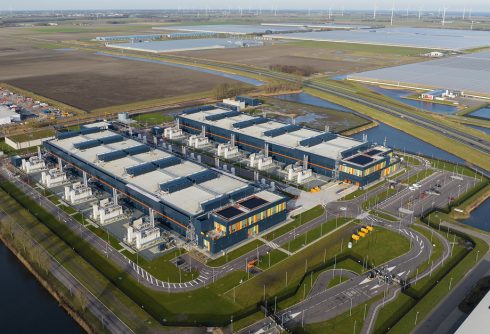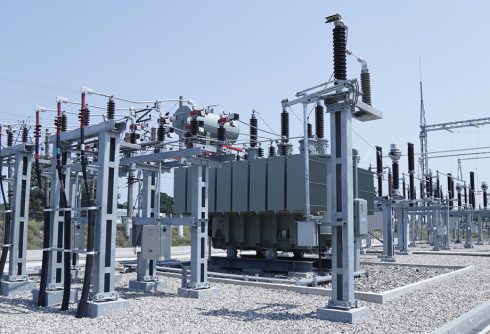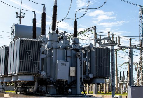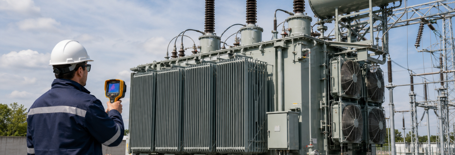
In March 2025, a catastrophic high-voltage bushing failure at the North Hyde substation caused a fire, cut power to more than 66,000 customers, and contributed to Heathrow Airport’s closure. The National Energy System Operator’s final review found that elevated moisture had been detected years earlier without an adequate response. The incident shows how an identifiable warning can develop into a major operational failure.
Recovery is harder in today’s market. The American Society of Civil Engineers reported transformer lead times of 80 to 210 weeks as of June 2024, with costs 60% to 80% higher than in January 2020. Preventing transformer failure requires disciplined decisions from specification through operation and replacement planning.
Recognize the Main Transformer Failure Modes
A transformer failure mode is the process that prevents a transformer or critical component from operating safely. Most problems fall into four categories: insulation and dielectric breakdown, overheating, electrical or mechanical damage, and accessory failures involving bushings or tap changers.
CIGRE’s transformer reliability survey identifies windings as a leading location for major failures, dielectric mechanisms as prominent across transformer types, and bushing failures as likely to produce severe external consequences. Patterns vary by voltage class, application, age, and environment, so maintenance should reflect each asset’s risk.
| Failure mode | Common cause | Early warning | Primary control |
|---|---|---|---|
| Insulation breakdown | Moisture, contamination, aging | DGA or oil-test changes | Oil testing and moisture control |
| Overheating | Overload or cooling failure | Rising oil or hotspot temperature | Load and cooling management |
| Winding damage | Fault forces or movement | Resistance or SFRA changes | Post-fault testing |
| Component failure | Seal, contact, or insulation wear | Leaks, heat, irregular operation | Targeted maintenance |
Prevent Insulation Breakdown and Moisture Damage
Moisture can enter through aging seals, breathers, bushings, maintenance openings, or poor storage. It reduces dielectric strength and accelerates degradation of oil and paper insulation. Contamination, partial discharge, and localized heating can compound the damage.
Warning signs include rising moisture-in-oil results, changing dissolved gas patterns, reduced dielectric strength, increasing acidity, and furan compounds associated with paper aging. Establish baseline oil results before energization and trend them over time. IEEE C57.104 guides dissolved gas analysis interpretation, while the current IEEE C57.152-2025 supports follow-up field diagnostics. Northfield’s guide to dissolved gas analysis and oil testing explains how layered testing can reveal developing problems.
Control Overheating and Electrical Stress
Sustained overloading, high ambient temperature, harmonics, blocked airflow, and failed cooling equipment can push temperatures beyond the intended range. Repeated heating accelerates insulation aging. Reduce risk by sizing units for realistic load growth, confirming cooling performance, and providing monitoring and alarm coverage.
Short circuits can deform windings, while lightning, switching surges, abnormal voltage, and repeated through-faults can weaken insulation and internal supports. Rising hotspot temperatures, unusual noise or vibration, infrared anomalies, and changing winding results should trigger investigation. After a significant fault, targeted testing can reveal hidden damage. See Northfield’s article on thermal stress, moisture, and transformer lifespan for more guidance.
Protect Bushings Windings and Tap Changers
Bushings can fail because of moisture ingress, internal tracking, seal defects, contamination, or deteriorated insulation. Oil leakage, cracking, carbon tracking, elevated temperature, or abnormal capacitance and power-factor results may indicate risk.
Windings can be damaged by short-circuit forces, loose clamping, insulation aging, or transportation movement. Sweep frequency response analysis, winding resistance, turns ratio, excitation current, and DGA provide complementary evidence. On-load tap changers need component-specific inspection and fluid testing because contact wear, carbon buildup, mechanism problems, and overheating may develop separately from the main tank.
Each vulnerable component should have a defined inspection method, alarm threshold, and escalation path.
Build a Condition-Based Prevention Plan
Transformer failure prevention begins before delivery. Specifications should address voltage, MVA, impedance, insulation level, cooling class, protection, monitoring, and future load. Manufacturing controls should include design review, material verification, drying oversight, inspection points, and factory acceptance testing.
Transportation and commissioning should include secure bracing, receiving inspection, leak checks, and baseline tests. Once energized, combine DGA, moisture testing, infrared surveys, load and temperature monitoring, bushing assessment, tap changer evaluation, and targeted offline diagnostics. Digital transformer monitoring can identify changing conditions between scheduled inspections.
Prioritize spending according to condition, criticality, consequence of failure, redundancy, and replacement lead time. This gives operators time to monitor, repair, refurbish, spare, or replace an asset before an emergency determines the schedule.
Learn More
Northfield supplies custom power transformers up to 400 MVA and 500 kV for utilities, data centers, renewable projects, and other critical facilities. Support includes engineering coordination, British-led quality oversight, factory acceptance testing, logistics, delivery, and optional installation and commissioning services. Northfield also provides shorter lead-time options than many prevailing market timelines. Contact Northfield to discuss specifications, failure-risk controls, and replacement planning.
Frequently Asked Questions (FAQ)
What are the most common transformer failure modes?
The main categories are insulation and dielectric breakdown, overheating, electrical or mechanical damage, and component failures involving bushings or tap changers. Several mechanisms may develop together. For example, moisture can weaken insulation, increase electrical discharge activity, and create additional heat.
What are the earliest signs of transformer failure?
Early warning signs include changing DGA results, rising moisture levels, abnormal temperatures, oil leaks, unusual noise or vibration, partial discharge, deteriorating bushing results, and irregular tap changer operation. Trends across several tests usually provide more useful information than a single isolated reading.
How does dissolved gas analysis help prevent transformer failure?
DGA measures gases produced by thermal and electrical activity inside the transformer. The gas type, concentration, and rate of change can indicate overheating, arcing, partial discharge, or insulation degradation. Trending results helps operators identify developing faults and determine when further testing or maintenance is needed.
Can transformer overloading cause permanent damage?
Yes. Sustained overloading increases winding and oil temperatures, accelerates paper-insulation aging, and may generate gases in the insulating liquid. Occasional loading above nameplate may be permitted under controlled conditions, but repeated or poorly managed overloads can reduce remaining life and increase failure risk.
How can transformer buyers reduce failure risk before delivery?
Buyers should confirm realistic loading requirements, insulation levels, cooling capacity, protection, monitoring, and future expansion needs. Manufacturing oversight, material verification, factory acceptance testing, transportation controls, receiving inspections, and commissioning baselines help identify defects before the transformer enters service.